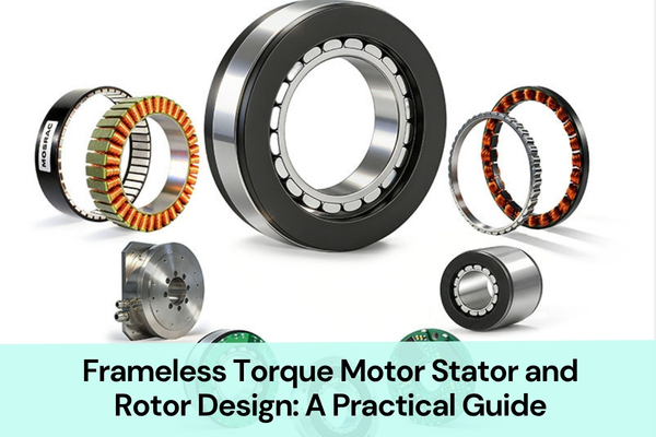
Why can a frameless torque motor deliver high torque density and precise motion in a compact space? The answer lies in how its stator and rotor are designed to work together.
1. Basic Structure of a Frameless Torque Motor
A frameless torque motor consists of two main parts:
Stator: The stator usually includes a stator core, three-phase windings, and an insulation system. A temperature sensor can also be added if needed.
Rotor: The rotor usually consists of permanent magnets and a rotor back iron. The magnets produce a magnetic field that interacts with the stator field to generate torque.
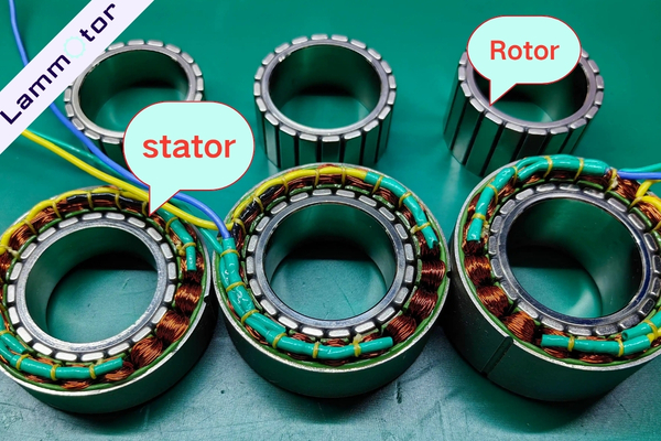
Unlike conventional motors with housings, frameless torque motor stator rotor assemblies are usually supplied as separate components.
During final assembly, we fix the stator to the stationary part of the equipment. The rotor is connected to the rotating part.
Bearings, shafts, and support structures are usually provided by the customer’s mechanical system.
2. Stator Design
The stator is one of the main electromagnetic components of a frameless torque motor.
It usually has a ring-shaped structure. It can be installed directly into a robot joint housing or another fixed part of the equipment.
Frameless torque motor stator rotor design requires a balance between torque density, winding space, core loss, heat dissipation, and manufacturing feasibility.
2.1 Stator Structure
Based on the core structure, stators can have two main types: full-circle stators and segmented stators.
Full-Circle Stator
A full-circle stator uses a complete ring-shaped core. The material is electrical steel laminations; the stacking method is normally interlocking. We can also provide in-die bonding.
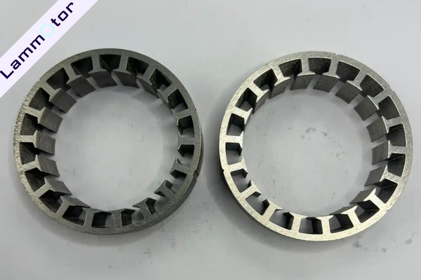
This structure provides good overall strength and stability.
However, winding space may be limited when the slot openings are narrow or the winding design is complex.
Segmented Stator
A segmented stator divides the core into separate teeth or core segments.
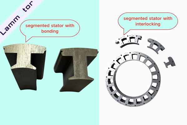
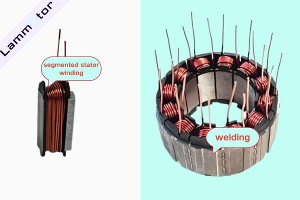
Each tooth can be wound individually. The segments are then assembled into a complete stator using a welding method.
This design provides better access during winding. It can also help increase the slot fill factor, especially for designs that require a high copper fill.
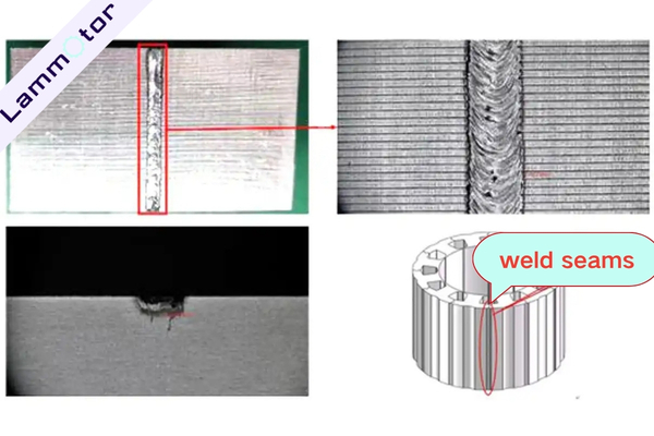
However, segmented stators require careful control of assembly accuracy, joint reluctance, roundness, and consistency.
The choice between a full-circle stator and a segmented stator depends on the electromagnetic design, winding process, manufacturing cost, and production volume.
2.2 Stator Core Materials
Non-oriented electrical steel (NOES) is a common material for frameless motor stator cores.
Common lamination thicknesses include:
- 0.20 mm
- 0.25 mm
- 0.35 mm
- 0.50 mm
Thinner electrical steel laminations can help reduce eddy current losses. They are especially useful for motors with higher electrical frequencies or strict core loss requirements.
3. Stator Insulation
Stator insulation protects the windings and helps prevent electrical failure.
For frameless motor stators, we provide epoxy coating and overmolding plastic.
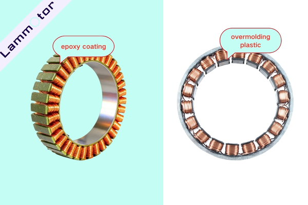
For high-temperature applications, the temperature class is Class H insulation (180°C) or other suitable insulation materials.
4. Stator Winding Design
In addition to the stator core, winding design plays an important role in motor performance.
The number of turns, wire cross-sectional area, slot fill factor, and end-winding length all affect motor resistance, inductance, back EMF, and temperature rise.
Winding selection is therefore an important step in frameless torque motor stator rotor design.
4.1 Fractional-Slot Concentrated Winding (FSCW)
Fractional-slot concentrated winding (FSCW) is a common winding method for frameless torque motors.
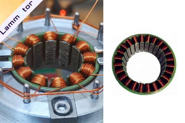
Unlike distributed windings, where coils span several stator teeth, concentrated windings are usually wound around individual teeth.
This design offers several benefits.
Shorter End Windings
Concentrated windings use less copper at the coil ends.
This helps reduce the axial length of the motor.
It is especially useful for robot joints with limited installation space.
Lower Winding Resistance and Copper Loss
Under similar design conditions, shorter wire length can reduce winding resistance and copper loss.
Flexible Winding Methods
Concentrated windings can be produced using needle winding, individual tooth winding, and other automated processes.
For segmented stators, each tooth can be wound separately before the full stator is assembled.
4.2 Wire Selection: Round Wire or Flat Wire?
Enameled copper wire is commonly suitable for stator windings.
The two main options are round wire and rectangular flat wire.
Round wire is widely used in frameless torque motors. Its manufacturing process is well established, and it offers flexible material and size options.
Flat wire can improve the use of slot space in certain stator designs.
Depending on the slot shape and winding layout, it may allow a higher copper fill factor.
The choice between round and flat wire should be based on the stator design and winding requirements.
4.3 Manual Winding vs. Automatic Winding
The winding process directly affects product consistency and manufacturing cost.
Manual Winding
Manual winding is suitable for prototypes, small production batches, and special designs that are difficult to produce with standard winding equipment.
It offers greater flexibility.
However, wire tension, winding arrangement, and product consistency must be carefully controlled.
Automatic Winding
Automatic winding is generally more suitable for mass production.
For example, a needle winding machine can control the winding process using preset parameters.
This improves repeatability and reduces manual work.
For segmented stators, individual tooth winding can also be used depending on the core design.
The final winding method depends on stator size, slot opening width, wire diameter, number of turns, and expected production volume.
After winding, electrical tests can be performed according to customer requirements.
These may include a hi-pot test, insulation resistance test, and other required electrical checks.
5. Stator Potting
Stator potting helps transfer heat generated by copper losses from the windings to the stator core.
The heat then passes through the motor housing to the external cooling system.
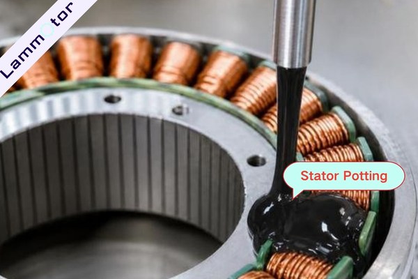
For frameless torque motor stator rotor thermal design, the thermal conductivity of the potting compound is an important factor.
Potting compounds can have thermal conductivity values ranging from around 0.5 to over 2.0 W/(m·K).
However, higher thermal conductivity is not always better.
Adding more thermally conductive filler usually increases the viscosity of the compound. This makes the potting process more difficult.
Small frameless motors with diameters below 50 mm often have narrow slot spaces.
High-viscosity potting materials may not flow easily into these areas.
Therefore, select the potting compound based on motor size, power level, cooling requirements, and processing conditions.
The following values are preliminary selection examples.
6. Rotor Design: Inner Rotor vs. Outer Rotor
Based on the position of the rotor relative to the stator, frameless torque motors can be divided into two main types: inner rotor and outer rotor designs.
6.1 Inner Rotor Design
In an inner rotor motor, the rotor is located inside the stator.
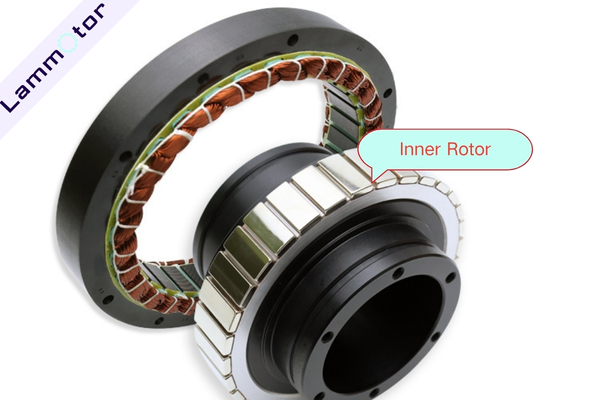
The stator surrounds the rotor.
This design offers a compact structure and can provide low rotational inertia.
Low rotor inertia is useful for fast starts, stops, and precise positioning.
Inner rotor motors are well suited for robot joints that need a fast dynamic response, such as waist and shoulder joints.
These joints must frequently change direction and perform movements such as turning and lifting.
Inner rotor designs can help meet these motion requirements.
They are widely used in humanoid robot applications.
6.2 Outer Rotor Design
In an outer rotor motor, the rotor is located outside the stator and rotates around it.
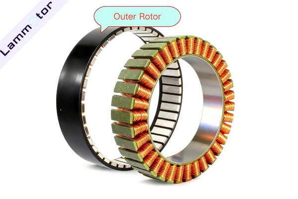
This structure allows a larger effective rotor diameter.
A larger working radius can help increase torque output when combined with a suitable electromagnetic design.
Outer rotor motors can be used in high-torque and heavy-load joint applications.
6.3 Permanent Magnet Material: NdFeB
Neodymium iron boron (NdFeB) is a common permanent magnet material for high-performance frameless torque motors.
It offers high remanence and a high maximum energy product.
These properties help produce a strong air-gap magnetic field within a limited motor size.
6.4 Rotor Back Iron Material
The rotor back iron can be made from steel with suitable magnetic properties, such as AISI 1010.
For designs that require lower rotor eddy current losses, a laminated structure can also be considered.
Need Custom Frameless Torque Motor Stator and Rotor Stacks?
Looking for a reliable manufacturer for your frameless torque motor project? Contact Lammotor for custom stator and rotor lamination stacks, as well as wound stator, magnets assemblies.
Send us your drawings and technical requirements. Our team will review your design and help you find the right manufacturing solution, from prototyping to mass production.