When you start designing a motor, the stator winding type is an unavoidable topic.
For beginners in motor design, seeing various complex winding methods, such as concentrated, distributed, single-layer, double-layer, and flat-wire windings, can be confusing.
Don’t worry! As an engineer with many years of experience in motor design and manufacturing, I am familiar with stator winding processes. Today, we will dive into the different types of stator winding to help you better understand them.
Classification by Stator Winding Shape and Installation Method
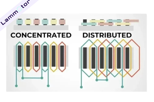
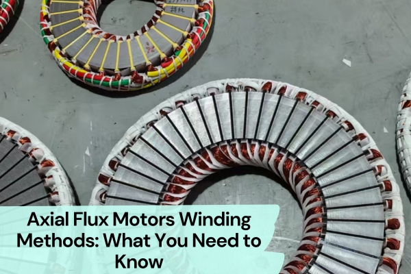
Stator windings are classified into two types: concentrated windings and distributed windings. This classification is based on the shape of the coil and the installation method. These two winding methods are suitable for radial flux stators and axial flux stators.
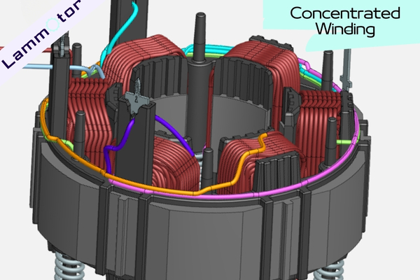
Concentrated Winding
Concentrated winding refers to all coils being concentrated on the same side of the stator, with each tooth carrying one winding. This structure is typically used for low-voltage, high-current applications. Key features of concentrated windings include:
- After the two windings of each phase are connected, the three phases can be connected in a star or delta configuration.
- Simple structure, usually composed of rectangular frame coils, which are wrapped and insulated, then varnished and dried before being installed on the stator’s protruding magnetic poles.
- Mainly used in DC motors, universal motors, excitation coils, and single-phase shaded-pole motor main windings.
- Due to smaller winding heads, concentrated windings are suitable for short motors, reducing Ohmic losses, making them easier to manufacture and lowering costs.
Distributed Winding
Distributed winding divides the winding into several parts, distributed across multiple iron cores to reduce magnetic leakage and improve efficiency. Its features include:
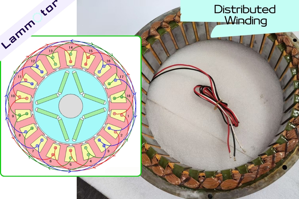
- By distributing the winding, magnetic leakage is reduced, increasing motor efficiency.
- It generates a smooth sinusoidal back EMF, lowering the harmonic ratio and reducing losses in the stator and winding laminations.
- It is especially suitable for high-efficiency applications, such as electric vehicles.
- Each coil is wound on at least two teeth, and the coil span can be selected according to the number of stator teeth and rotor pole pairs, typically spanning 3, 4, 5 teeth, or more.
End Winding Differences
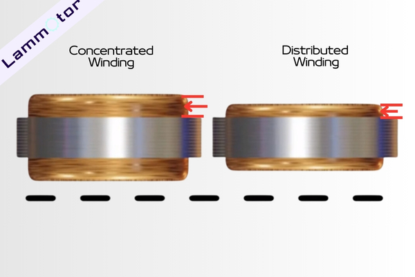
In distributed windings, the top and bottom of the winding overlap, creating larger winding heads, increasing volume and complexity.
In contrast, concentrated windings have smaller winding heads, making them suitable for smaller motors.
Back EMF Characteristics Comparison
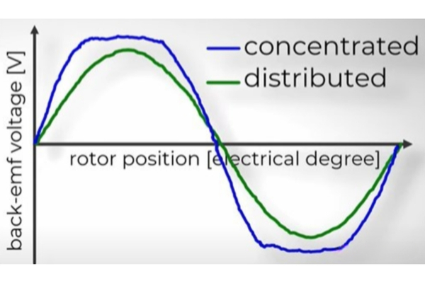
Distributed windings produce a smooth sinusoidal back EMF, while concentrated windings produce a trapezoidal waveform. While concentrated windings generate higher torque, they also produce more harmonics, leading to higher losses and NVH (Noise, Vibration, Harshness) issues.
Therefore, high-efficiency applications like electric vehicles mostly use distributed windings to reduce losses and improve overall performance.
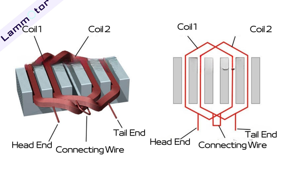
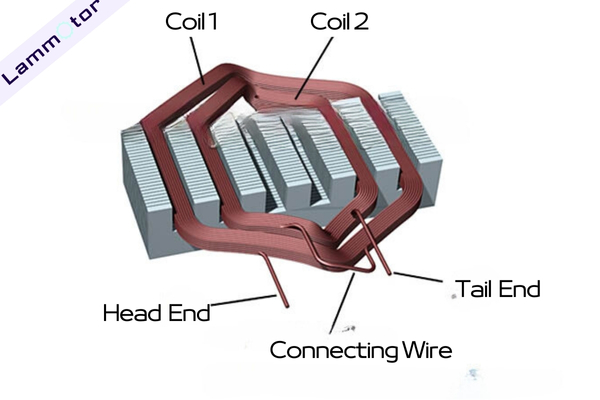
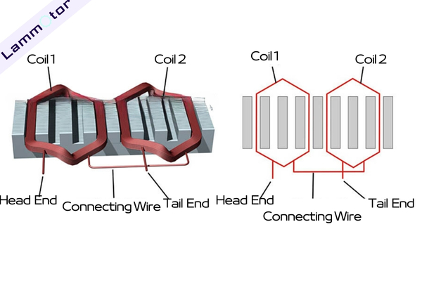
Classification by Winding Layers
Motors can be classified into single-layer and double-layer windings based on the number of winding layers. In single-layer windings, each slot carries one phase, while in double-layer windings, each slot contains two phases.
Single-Layer Winding
Single-Layer Lap Winding:
Coils of the same phase are stacked together, with the next coil stacked behind the previous one.
Single-Layer Concentric Winding:
Coils of the same phase are arranged concentrically.
Single-Layer Chain Winding:
Coils of the same phase are connected in a chain.
Double-Layer Winding
Double-layer windings are coils installed in two layers within the iron core slots.

Advantages
- Improved Air-Gap Magnetic Field: By selecting the most favorable pitch, double-layer windings can effectively reduce high-order harmonics in the air-gap magnetic field, making the rotating magnetic field closer to a sine wave. This improves motor starting and running performance.
- Easier to Manufacture: All coils have the same shape and size, making production more standardized and easier.
- More Parallel Branches: Double-layer windings can form more parallel branches, making them suitable for high-power motors.
- Neat End Windings: Coils at the slot ends overlap uniformly, making the end windings neat, and improving motor appearance and structural stability.
Disadvantages
- Inter-Layer Insulation Requirements: Each layer of windings requires insulation, increasing design and production complexity.
- Low Slot Space Utilization: Double-layer windings occupy more slot space, leading to lower slot space utilization.
- Difficult Winding Insertion: Inserting two layers of winding into each slot is difficult and may lead to inter-phase short circuits.
Double-layer windings are typically used in larger three-phase asynchronous motors (usually above 10 kW) that require higher power output.
Classification by Stator Winding Magnetic Pole Formation
According to the relationship between the number of motor poles and the actual magnetic poles formed by the winding distribution, stator windings are divided into salient-pole and non-salient-pole types.
Salient-Pole Winding
Salient-pole windings arrange coils between pole pairs so that each pole pair has an independent magnetic pole. This structure is commonly used in DC motors and permanent magnet synchronous motors. Its main advantages are:
- Efficient electromagnetic torque, with stronger magnetic fields between poles.
- Each magnetic pole is controlled independently, allowing precise adjustments.
In salient-pole windings, to alternate the polarity of the poles (N and S), the current direction in adjacent coils must be opposite. This requires connecting coils in a series with opposite ends joined (end-to-end connection).
Non-Salient-Pole Winding
Non-salient-pole windings have an odd number of coils, with the same number of conductors in each coil. The winding alternates along the magnetic centerline (non-salient line), hence also known as the non-salient-pole winding.
In non-salient-pole windings, all coils create magnetic poles with the same polarity, and the current direction is the same. Adjacent coils are connected end-to-end in series.
This design makes non-salient-pole windings structurally simple and evenly distributed magnetic fields, making them suitable for specific motor design needs.
Flat-Wire Winding Technology
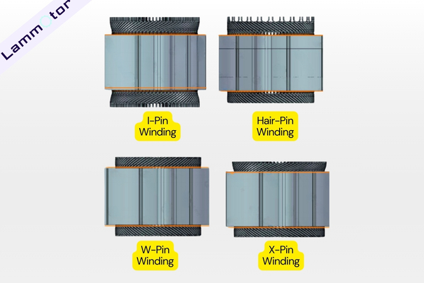
Current flat-wire motor windings include Hair-Pin windings (U-Pin), I-Pin windings, W-Pin windings (continuous-wave windings), and X-Pin windings.
Hair-Pin and I-Pin Winding
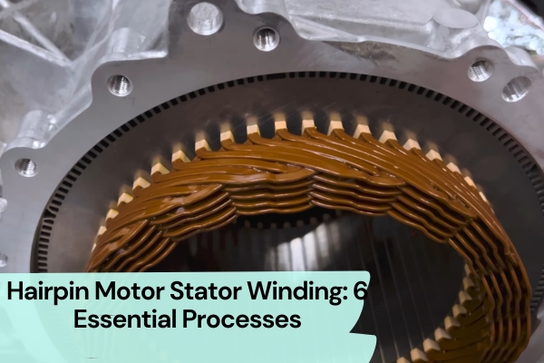
Hair-Pin and I-Pin are the most mature flat-wire winding techniques.
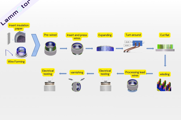
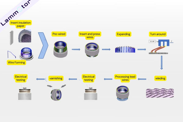
The conventional Hair-Pin winding process requires insulating paper forming and insertion, winding wire forming, wire insertion, flaring, twisting, cutting, end welding, three-phase wire welding, electrical test 1, coating, dripping, and electrical test 2.
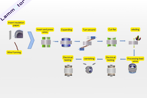
The I-Pin process has fewer pre-forming processes than the Hair-Pin process. And the single-slot assembly saves some assembly reserved space compared to the Hair-Pin winding form, so the I-Pin slot fill rate is higher, but it requires cutting and welding at both ends, which is currently mainly done by Bosch.
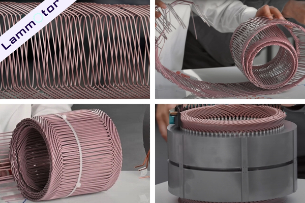
W-Pin Continuous-Wave Winding
W-Pin Continuous-Wave Winding is an innovative design that forms the winding as a whole, without the need for welding at both ends. The insulation layer of the wire meets the creepage requirements for high-voltage platforms, and W-Pin winding requires fewer devices, leading to lower equipment investment.
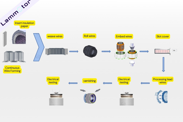
At the same time, by skipping the coating process, W-Pin windings have significantly lower end height compared to Hair-Pin products, with the same wire diameter and pitch.
However, the process development for W-Pin is relatively complex, especially the continuous winding forming technology and wire insertion technology. These are challenges that limit large-scale production.
Regarding the wire insertion process, there are two main types based on the insertion direction: inner diameter insertion and outer diameter insertion.
Inner Diameter Insertion:
By applying force between the copper wire and the expanding sheet, the copper wire uniformly expands outward and fits into the iron core slots while ensuring that the insulation paper is not damaged.
This method requires the slot width to be larger than the slot bottom width. But compared to Hair-Pin technology, the slot fill rate is reduced by 10-15%, and there is a potential risk of magnetic leakage.
Outer Diameter Insertion:
First, the winding is wound on the teeth, and then an iron core sleeve is placed on the outer side. The inner and outer circular iron cores are connected by welding.
This method effectively solves the problem of winding shaping after being pressed into the core. It prevents winding damage, and improves stator slot issues, reducing tooth-slot torque.
However, this process only allows welding on the surface of the iron core, which may affect the core’s strength.
Currently, Lucid Air uses this continuous-wave winding technology to improve the motor’s efficiency and reliability.
X-Pin Winding
The X-Pin and short-Pin processes mainly come from the X-Pin winding technology developed by United Electronics.
X-Pin winding technology significantly reduces copper loss in motors by optimizing the welding ends. This improves motor efficiency.
Research by United Electronics shows that compared to I-Pin windings, X-Pin can shorten the motor length by 43%. Compared to Hair-Pin, it reduces length by 25%. Compared to W-Pin, it shortens length by 8%.
With high slot fill rate, X-Pin winding not only reduces the overall motor length but also saves copper wire. This helps make the motor more compact.
X-Pin’s process doesn’t require straight segments, so it doesn’t need end cutting like Hair-Pin and I-Pin. However, X-Pin has high requirements for wire forming accuracy and consistency. The paint removal length is only a few millimeters, so laser paint removal is required. Without straight segments, twisting and welding become major challenges for large-scale X-Pin production.
Short-Pin Process
The short-Pin process is an improvement on the Hair-Pin and I-Pin processes.
Unlike X-Pin, which completely removes straight segments, the short-Pin process keeps some straight segments.
By improving the welding process, short-Pin windings ensure better overcurrent capacity, pulling force, and reduced thermal impact on the winding coating.
This improvement balances process complexity and motor performance, making it another important winding technology option.
Conclusion
In conclusion, stator winding is a critical part of motor design. It determines the motor’s performance and reliability. I hope this blog helps you gain a clearer understanding of stator windings.
If you have any needs in stator core manufacturing, varnishing, or winding services, feel free to contact us. We offer professional solutions!