When it comes to buzzwords in new energy vehicle technology, what comes to your mind?
800V platform? SiC power devices? Or hub motors?
Among the hottest trends, the hairpin motor (flat wire motor) is certainly leading the pack. Ever since Tesla adopted this technology, discussions surrounding hairpin motors have only intensified.
We’ve previously published several technical articles on hairpin motor technology—such as flat wire techniques used in NEV drive motors. Feel free to check them out if you’re interested.
For those new to motor technology, the difference between round wire and flat wire motors might seem like just a change in appearance or a few numbers. But for manufacturing companies, this change reshapes the entire production process and the equipment required.
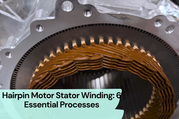
In actual production, hairpin motors demand higher stability and pass rates compared to traditional round wire motors. Today, let’s explore the six core manufacturing processes that dominate the production of hairpin motor stator.
Overall Hairpin Stator Production Workflow
The typical process flow for producing a hairpin stator includes:
Slot paper insertion → Hairpin forming → Hairpin insertion → End ring shaping → End ring welding → Star point connection → Insulation treatment for weld points.
Notably, wire forming and paper forming/insertion are performed in parallel.
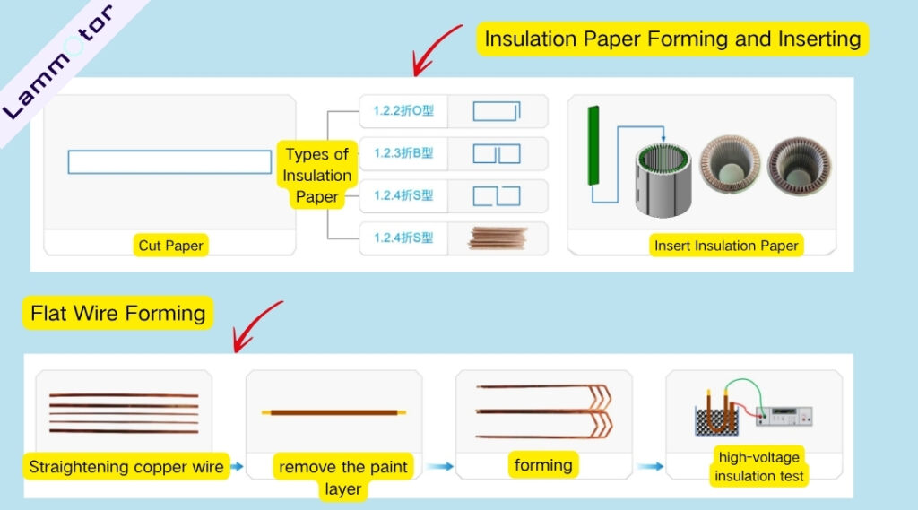
1. Slot Paper Insertion
Insulation paper is placed between the stator slots and conductors to isolate different phase windings and prevent short circuits between the wire and the core.
This process usually involves shaping, cutting, and inserting insulation paper. Common paper forming techniques include cold forming and hot forming.
Slot paper shapes include O-type, C-type, B-type, and S-type. Among them, O-type is the most widely used. B-type and S-type offer better insulation but involve more complex manufacturing steps and lower copper fill rates, resulting in poor stability.
For some motors, two layers of insulation paper are needed between adjacent phase conductors within a slot. This increases insulation volume, reduces power density, and poses challenges for automation since current equipment struggles to insert dual-layer paper efficiently—this remains a major obstacle to automated hairpin stator manufacturing.
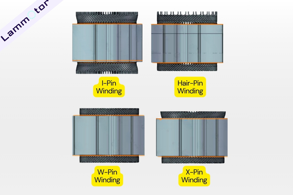
2. PIN Coil Forming
Stator hairpins are typically produced using processes like I-PIN, Hairpin, or Wave Winding.
The steps include straightening, paint removal, cutting, and shaping. Paint stripping is typically done using laser or traditional mechanical methods. While traditional methods are cheaper, they can damage the copper wire and leave residue.
Forming methods include stamping and spring machine forming. Although spring forming is more expensive, it minimizes damage to the copper.
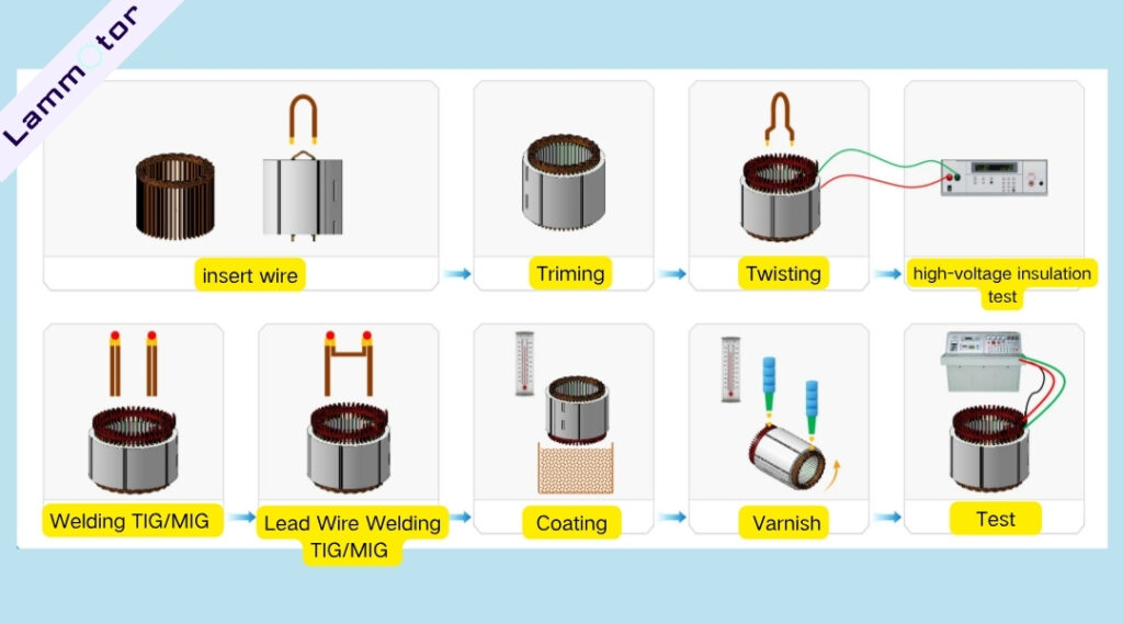
3. Hairpin Insertion
Hairpins are inserted into a form jig and then collectively inserted into the stator core and pressed into their designed positions.
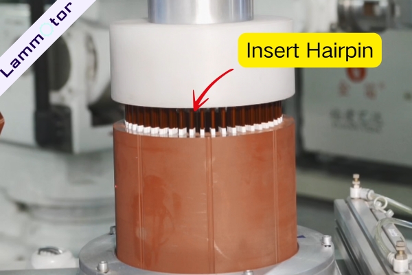
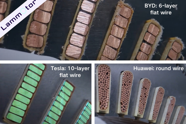
This technology has advanced from 2-layer and 4-layer insertions to modern 6-layer, 8-layer, and even 10-layer designs.
In our earlier article, Comparison of Motor Stator and Rotor Technologies of Tesla, BYD, and Huawei, we mentioned that BYD uses a 6-layer hairpin winding, Tesla employs a 10-layer structure, and Huawei still uses round wire windings.
4. Spreading, Twisting, and Welding
Spreading Process
The stator is positioned at the flaring station where tooling expands all layers of hairpins—except the innermost two—by pulling them outward.
Twisting Process
After flaring, the inner two layers are aligned with a twisting mechanism. The tool grips and rotates the conductors in opposite directions, completing the twist.
Welding Process
Laser welding and TIG (argon arc) welding are currently the main techniques. These methods create instant high temperatures to melt copper and form connections between windings.
Some companies are experimenting with cold metal transfer (CMT) welding and other alternatives.
However, both laser and TIG welding have two major drawbacks:
- The high heat can damage the insulation film on enameled wire, reducing reliability.
- Each hairpin stator contains many joints, and welding them individually slows down production significantly.
5. Coating and Varnish Impregnation
Coating materials come in powder and liquid forms. Common varnish processes include traditional dip varnish, vacuum impregnation, vacuum pressure impregnation (VPI), trickle varnishing, and EUV varnish techniques.
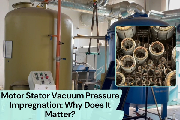
6. Vacuum Potting of the Stator
Thermal management has long been a challenge in electric motor design. As the demand for higher power density and longer range grows, so does the need for better cooling.

Traditional varnish impregnation struggles with heat dissipation and durability. In response, vacuum potting has become a mainstream solution.
An ideal potting resin must:
- Have good fluidity before curing to fill all winding gaps, forming a smooth and balanced outer surface.
- Provide strong adhesion to the windings, with high mechanical strength and resistance to thermal shock.
- Offer excellent thermal conductivity to transfer heat quickly and reduce internal stresses.
- Ensure good electrical insulation and oil resistance. Once potted, the stator becomes a single sealed unit with better heat dissipation, structural stiffness, vibration damping, and resistance to moisture, shock, and electrical corona.
Want to learn more about hairpin motor stator winding?
Hairpin motor stator winding is no longer just about winding copper into a core—it’s a full-fledged integration of precision engineering, materials science, and process optimization. Each step, from paper insertion to vacuum potting, directly affects motor performance, efficiency, and long-term reliability.
Are you working on a motor project that requires hairpin technology? Or maybe you’re curious how our factory handles these processes?
Let’s talk! Feel free to reach out—we’re happy to provide expert support or stator winding services tailored to your needs.