Is the drive motor underperforming because of heat? What are the common methods for cooling the drive motors? and do you know Borgwarner stator oil cooling technology?
As the need for high power density and high reliability grows in new energy vehicles, motor cooling has become a major concern. You may ask: water cooling is already mature, so why are more manufacturers turning to oil cooling? What is the future of oil-cooled motors?
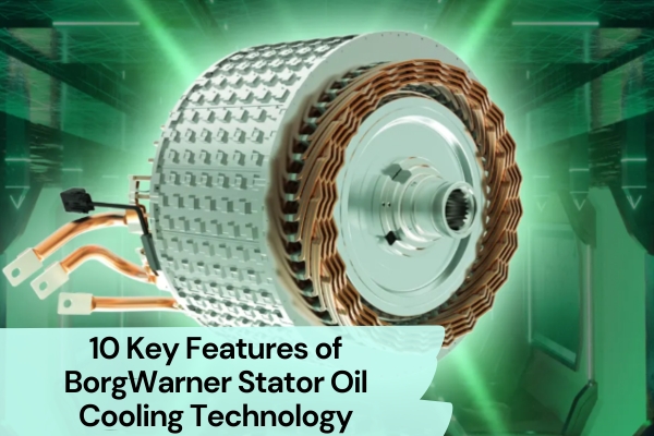
This article introduces the innovative Borgwarner stator oil cooling technology, which redefines oil path layout. It brings higher cooling efficiency, a smaller structure, and greater power density to drive motors.
1. Flexible Core Matching
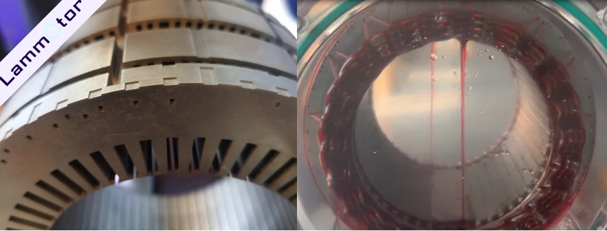
The stator in Borgwarner’s oil-cooled motor adopts a radial spray oil circuit design. Oil sprays from the outer edge toward the center, making use of the core’s effective thickness and angle layout. This lets the cooling oil directly pass through the stator core and windings, quickly and evenly removing heat inside the motor.
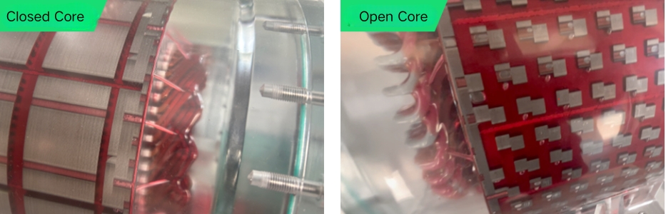
One key benefit of this design is its flexible compatibility with different stator cores. It can match either open or closed core types. When paired with an open core, the motor housing forms a closed oil circuit. This reduces the motor’s diameter, overall size, and weight.
2. Oil Spray Hole Design
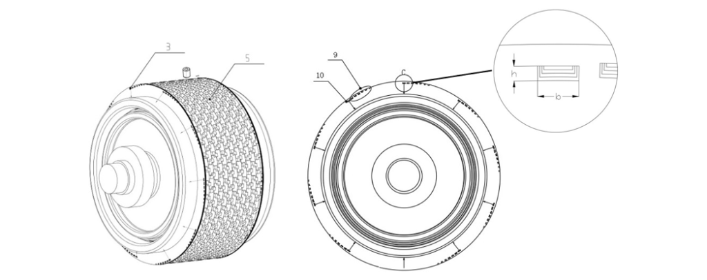
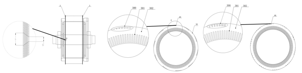
According to Borgwarner’s patents, the spray holes feature four different designs. These holes are arranged one after another along the side of the spray part facing the stator core. Each hole axis is spaced apart, forming a tilted spray path.
The spray channel is slanted from the end of the spray part toward the winding ends. This ensures the cooling oil directly sprays onto the stator winding ends. Multiple spray holes are placed in sequence on the side of the spray part facing the core. Distances between hole axes are designed to optimize spray coverage. Some spray holes are located at the oil inlet or outlet ends, with widened sections to stabilize flow.
The hole placement can vary across silicon steel sheets. Their distance from the stator core axis may differ to allow flexible spray coverage. Spray holes can also be arranged in multiple rows radially. In each row, holes are spaced along the circumference, with step-like distances from the axis to enhance coverage.
3. No Extra Oil Circuit Parts
The system does not need oil tubes, spray rings, or sealing rings. This simple assembly method reduces system cost effectively.
4. Oil Path Does Not Affect Magnetic Circuit
The oil circuit design does not interfere with the magnetic path. It has no negative impact on the motor’s electromagnetic performance.
5. Pin-Fin Cooling Structure
The design uses a Pin-Fin heat dissipation structure. It offers a large contact area and high cooling efficiency. The Pin-Fin design changes oil flow from laminar to turbulent, increasing heat transfer. This significantly boosts the cooling performance of the oil.
Using this method, current density can increase by 10–15%. At the same time, motor size can shrink by around 5–10%, further increasing power density.
6. Series Oil Circuit Design
The cooling oil path connects the stator core and winding ends in series. Each part uses the full oil flow to cool down, making better use of the cooling oil.
When oil enters the stator core’s heat dissipation channel, the small step-like spray paths create oil resistance. This allows oil to fill the entire channel space and touch all surfaces, which improves heat transfer.
After cooling the core, the oil sprays onto the winding ends. Compared to parallel oil pipe designs, this series layout needs less flow to achieve better cooling results.
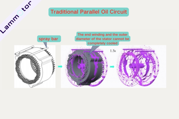
Compared with the Traditional Parallel Oil Circuit
Unlike traditional parallel spray systems, this design needs less oil but cools more evenly and effectively. Especially when the welded ends are not coated, the cooling results become even more noticeable.
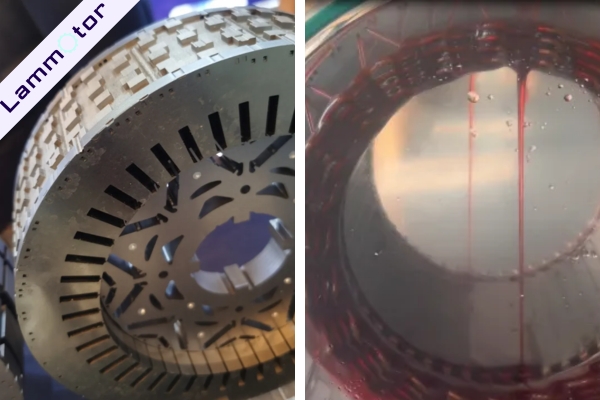
7. Centripetal Spray Design with Laminated Cores
The end section uses optimized laminated cores to create a centripetal oil spray path. All spray holes point from the outer ring toward the center. By adjusting the shape of the laminations, the spray angle can match different motor sizes. This ensures full oil coverage of the windings, with no blind spots and better cooling. When the welded ends are not coated, the effect is even better.
8. Fixed Spray Angle
The spray angle remains unchanged. Once the oil flow reaches the design value, the angle stays fixed even as flow increases. This allows engineers to optimize flow rates for different working conditions.
9. Controllable Directional Spray
By adjusting the oil path, different spray holes can be tuned. The top holes can receive more oil, while the lower holes get less. This results in more even cooling throughout the motor.
10. Adjustable Oil Inlet Position
The oil inlet can be placed at the top, bottom, or side. This flexibility helps optimize the layout of the whole system.
In today’s race for electric drive technology, the key to performance is heat control. Borgwarner stator oil cooling technology uses a compact design, efficient spraying, series cooling, and flexible integration to lead the new trend in oil-cooled motor cooling.
Major suppliers are shifting their focus from water cooling to oil cooling. Unlike traditional water-cooled motors, oil-cooled motors use different mediums and heat exchange methods. Only by controlling heat can we fully unlock the motor’s output potential and improve its reliability.
If you would like to learn more about new energy vehicles motor, please click the link.