Have you ever wondered how electric vehicles achieve such precise motor control at high speed? The answer lies in the resolver. This position sensor plays a vital role in detecting the exact rotor angle and speed of a motor, then sending this information back to the controller.
Without an accurate resolver, even the most advanced motor would fail to deliver smooth performance, efficiency, and safety.
What is a Resolver?
A resolver is an inductive rotary transformer that converts angular displacement into electrical signals. It is often described as a displacement sensor, but it can also perform coordinate transformations and function calculations.
The resolvers are made of a stator and a rotor. The stator winding acts as the primary side of the transformer, connected to the excitation voltage. The rotor winding acts as the secondary side, where induced voltage is generated through electromagnetic coupling.
Structure of Resolvers
A resolver is designed much like a small synchronous motor. Its main parts include:
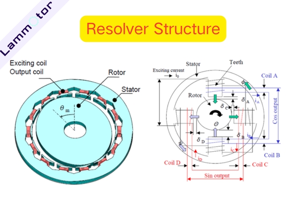
- Stator – built from laminated silicon steel sheets, usually 0.35 mm or 0.5 mm thick.
- Rotor – connected to the motor shaft, rotating along with it.
- RDC (Resolver-to-Digital Converter) or DSP – converts analog sine and cosine signals into digital signals.
The stator is excited by an AC supply, and the induced signal in the rotor changes according to displacement. The resolver outputs a pair of unique sine and cosine signals for each angle, which allows the system to calculate the exact rotor position and speed.
Types of Resolvers
1. Brushed Resolver
The rotor winding is connected through slip rings and brushes. Although simple and compact, this design suffers from poor reliability and short service life due to mechanical wear. Today, it is rarely used.
2. Brushless Resolver
A brushless resolver is made up of two main parts: the resolver body and an additional transformer. The cores and coils of the additional transformer are ring-shaped, fixed separately to the rotor shaft and the housing, with a radial air gap between them.
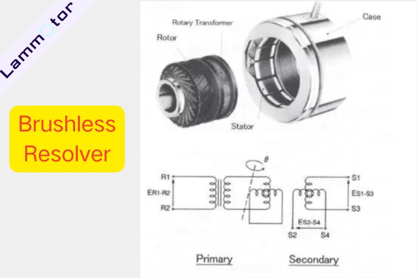
The rotor winding of the resolver body is connected to the primary coil of the additional transformer. The signal from the rotor winding is transmitted indirectly through electromagnetic coupling, via the secondary coil of the additional transformer.
This design eliminates the problem of poor contact between brushes and slip rings, which improves reliability and extends service life. However, it also increases the size, weight, and cost of the resolver.
Currently, there are two common types of brushless resolvers:
3. Toroidal Transformer Type Resolver
This design achieves true brushless and contactless operation. The right side of the device looks like a traditional resolver with stator and rotor windings for signal conversion. On the left side, a toroidal transformer is placed, with one winding on the stator and one on the rotor, arranged concentrically.
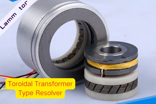
The winding on the rotor side of the toroidal transformer is connected to the signal-conversion winding on the rotor. The input and output of the electrical signal are completed through this toroidal transformer.
4. Reluctance Type Resolver
In this type, both the excitation winding and the output windings are placed together in the stator slots and remain fixed. However, the design of the excitation winding and the output windings is different. The two-phase output signals still follow a sine wave pattern with a 90° electrical phase difference.
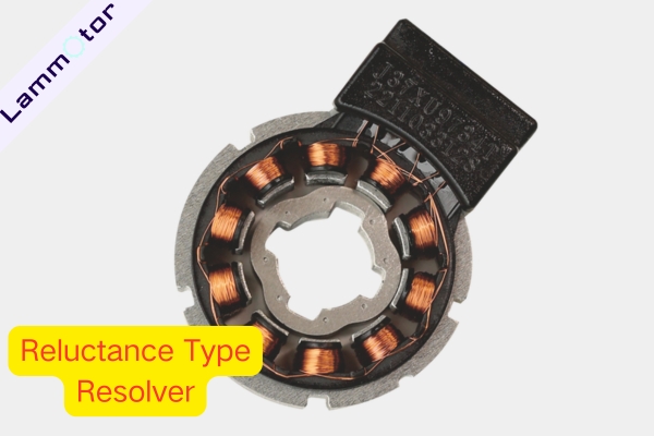
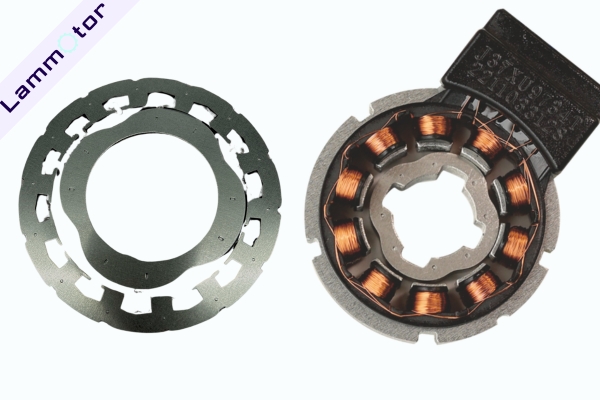
The rotor has a specially designed magnetic pole shape that makes the air-gap magnetic field close to sinusoidal. The rotor’s shape also determines the number of pole pairs and the waveform of the air-gap field.
Reluctance resolvers are usually supplied as separate components instead of a fully assembled unit. Users need to assemble and match them on their own.
How Does a Resolver Work?
At its core, the resolver functions like a transformer. It shares similar parameters such as rated voltage, frequency, and turns ratio.
However, unlike a normal transformer, its primary and secondary sides move relative to each other. As the angle changes, the output voltage waveform changes in amplitude.
In a reluctance resolver, the stator contains one excitation winding and two output windings fixed in slots. The rotor shape determines pole pairs and the sinusoidal distribution of the air gap flux. As the rotor turns, the two-phase windings generate sine and cosine signals, enabling accurate position and speed measurement.
Applications of Resolvers
Resolvers are electromagnetic position sensors widely used in:
- Aerospace
- Industrial automation
- CNC machine tools
- Robotic joints
- Servo systems
They provide reliable feedback in environments where high temperature, vibration, or electromagnetic interference make optical encoders unsuitable.
Well-known international resolver manufacturers include LTN (Germany), Siemens (Germany), Tamagawa (Japan), ATAS (Czech Republic), TE Connectivity (USA), and Harowe (USA). In China, leading suppliers include Huaxuan (Changzhou), Yingshuang (Shanghai), and Changyou Automation.
Resolver vs Encoder
Strictly speaking, a resolver is not an encoder, because their working principles differ.
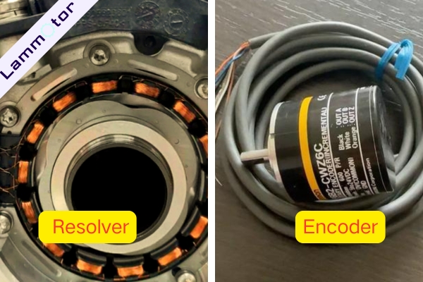
- Resolver: Analog device. Requires an RDC to interface with digital systems. Best choice for extreme environments where reliability is more important than precision.
- Encoder: Digital device. Provides high accuracy and fast communication. Preferred in clean environments with high-speed automation.
| Feature | Resolver | Encoder |
| Working Principle | Electromagnetic induction (transformer principle) | Photoelectric / magnetic code |
| Signal Type | Analog signal (Sin/Cos modulation) | Digital signal (pulse, serial data, etc.) |
| Signal Processing | Requires external RDC (Resolver-to-Digital Converter) | Direct digital signal output, no extra conversion |
| Anti-interference Ability | ★★★★★ (Strong resistance to electromagnetic interference, vibration, high temperature) | ★★★★☆ (Magnetic encoder strong, photoelectric encoder weak) |
| Environmental Adaptability | Excellent (high temperature, oil, vibration, shock) | Average (photoelectric encoder sensitive to contamination, magnetic encoder sensitive to harsh environments) |
| Accuracy | Medium to high accuracy (typical ±5 arcmin, high precision ±1 arcmin) | Ultra-high accuracy (photoelectric encoder absolute accuracy up to ±0.1 arcmin) |
| Resolution | Depends on RDC chip (commonly 12–16 bits) | Directly depends on code disk (can reach 24 bits or higher) |
| Cost | Lower (resolver body is simple, but needs RDC chip externally) | Higher (high-resolution photoelectric encoders are expensive) |
| Typical Applications | Automotive drive motors, aerospace, military, heavy machinery | Industrial robots, digital control, intelligent equipment, precision manufacturing |
In short:
- For automotive, aerospace, and defense applications, choose the resolver.
- For industrial automation and precision manufacturing, choose the encoder.
Customize Motor Stator and Rotor of Resolvers
The resolver remains one of the most trusted solutions for motor position sensing, thanks to its durability, reliability, and ability to operate in harsh conditions. From electric vehicles to aircraft and industrial robots, the resolver continues to play a critical role in motion control systems.
Would you like to explore custom resolver stator and rotor core manufacturing for your project?
Feel free to contact us. Our team specializes in producing high-quality motor lamination stacks tailored to your requirements. Let’s build your next-generation resolver together.