Have you ever wondered how a large high-voltage motor is actually built?
In industries like wind power generation, mining, steel, and petrochemicals, these motors act as the “heart” of the equipment. Behind their powerful operation lies a complex and precise High-Voltage Motor Manufacturing process.
As an experienced High-Voltage Motor Core manufacturer, we know that every lamination, every winding, and every vacuum varnishing step directly determines the motor’s performance and lifespan.
This article walks you through the complete journey—from core fabrication to the final factory test—revealing how a high-voltage motor comes to life.
1. High-Voltage Motor Core Manufacturing Process
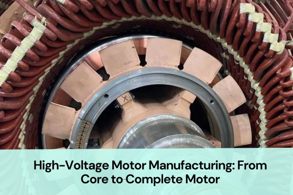
The performance of a High-Voltage Motor depends heavily on the quality of its core.
The High-Voltage Motor Core serves as the magnetic circuit backbone—it guides magnetic flux, stores energy, and supports the stator winding. Its accuracy and material properties directly affect efficiency, temperature rise, and noise.
Let’s explore how the core is made step by step.
Step 1: Raw Material Preparation
Everything starts with high-grade electrical steel sheets.
Depending on motor power and voltage levels, we usually use cold-rolled non-oriented silicon steel with a thickness of 0.35 mm or 0.5 mm.
Before production begins, we test each batch for magnetic permeability, iron loss, and insulation coating quality to meet high-voltage motor insulation and magnetic performance requirements.
Most materials come from well-known electrical steel suppliers such as Baosteel, Shougang, and WISCO, ensuring stable magnetic properties and consistent batches.
Step 2: Sheet Cutting
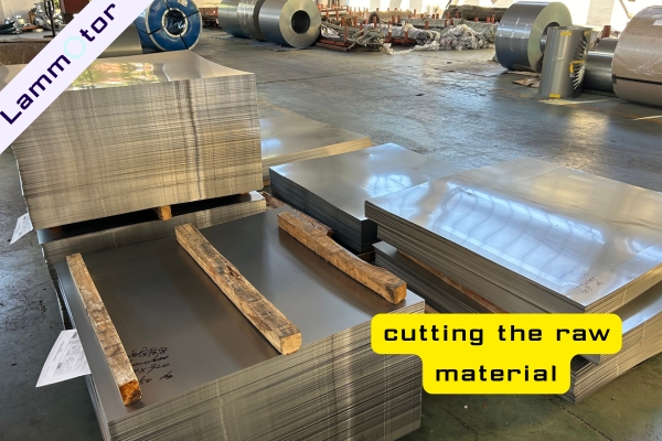
The steel coils are unrolled and cut into pieces according to die dimensions using automatic shearing lines.
Although this step looks simple, it directly affects stamping precision and lamination consistency.
After cutting, each piece is cleaned and marked to maintain a consistent magnetic direction during punching
Step 3: Compound and Single-Slot Stamping
Next comes stamping—a crucial stage in High-Voltage Motor Core production.
For large High-Voltage Motor Stators, a compound press forms the outer diameter, followed by single-slot punching to cut slots, inner holes, and positioning features.
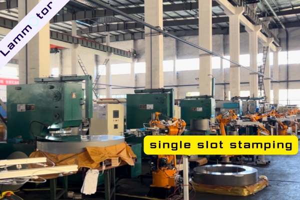
Tooling cleanliness and sharp edges are essential to avoid burrs that can affect stacking quality.
For prototypes or small quantities, we will use laser cutting.
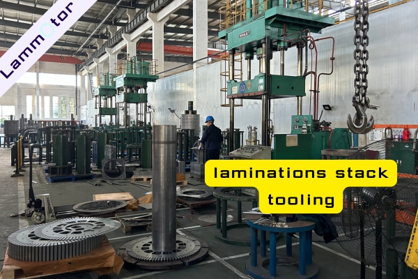
Step 4: Stacking Fixture Preparation
To ensure dimensional accuracy and magnetic alignment, a dedicated stacking fixture is made before assembly.
This fixture includes a steel shaft, end plates, and tightening bolts, keeping every lamination centered during stacking.
Its precision determines roundness and perpendicularity, so all components are CNC-machined and precisely calibrated.
Step 5: Lamination Stacking
This is the most critical step in High-Voltage Motor Core Manufacturing.
Technicians manually stack laminations on the fixture, inserting ventilation plates at intervals for cooling.
After stacking, a press is used to compact the core, ensuring the correct height, flatness, and concentricity.
Step 6: Welding
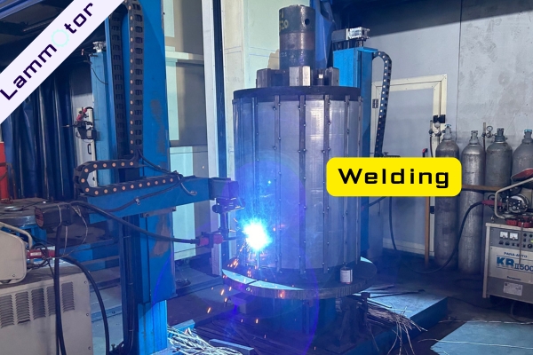
Once compacted, the core is welded at the ends to secure it with the end plates and compression rings.
Proper heat control prevents insulation layer damage.
After welding, each core is visually inspected to ensure smooth and uniform welds.
Step 7: CNC Turning
The welded core is then processed on a CNC lathe (vertical or horizontal) to machine its outer diameter precisely.
This ensures perfect fit during stator housing assembly.
Low-speed cutting and controlled temperature prevent loss of magnetic properties.
The result is a precisely machined High-Voltage Motor Core ready for assembly.
Step 8: Inspection and Quality Control
Before moving forward, each core undergoes strict dimensional and visual inspections:
- Outer and inner diameter concentricity
- Stack thickness and compression ratio
- Weld seam quality
Only qualified High-Voltage Motor Cores proceed to the next phase.
2. High-Voltage Motor Winding Process
After the core is finished, the next step—High-Voltage Motor Winding—begins.
This stage is the most technical and labor-intensive, converting electrical energy into magnetic energy that drives the rotor.
The process includes three main stages: winding, taping, and forming.
Step 1: Coil Winding
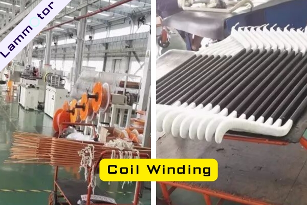
The conductor type depends on motor voltage and power rating.
Commonly used wires include dual-imide flat wire, single-imide flat wire, and twin parallel wires, all offering excellent heat, voltage, and mechanical resistance.
Technicians wind each coil precisely on dedicated machines with tension control, ensuring uniform turns and spacing.
The result is a neat bobbin coil, ready for forming.
💡 Tip: Even tension and consistent winding layout are crucial to avoid local heating and electrical imbalance.
Step 2: Coil Taping and Insulation
Each wound coil is then wrapped with insulation tape to enhance mechanical strength and electrical insulation.
Experienced workers use shrink tape, waxed cloth tape, polyester, or fiberglass tape for this purpose.
The goals are:
- Protect insulation during handling
- Improve inter-turn dielectric strength
- Secure the coil for later forming
Modern facilities may also use automated taping machines for consistency.
After taping, the coils look neat and smooth—almost like crafted insulation components.
Step 3: Coil Forming
The taped bobbin coils are expanded and shaped into rectangular or diamond forms to fit the stator slots.
This process requires precision and experience.
Operators use dedicated fixtures or forming machines to adjust coil geometry and ensure smooth bends at exact angles.
Improper stretching can damage insulation, so skillful handling is vital.
Once formed, the coils are ready for manual insertion into the High-Voltage Motor Stator.
3. Stator and Rotor Winding Insertion
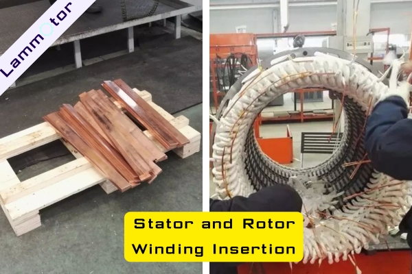
This phase demands patience and expertise.
Unlike small motors that use automatic insertion, large High-Voltage Motor Stators require manual coil insertion.
Because the coils are large and stiff, manual insertion prevents damage to insulation and ensures perfect alignment.
Workers place slot insulation (such as Nomex or mica paper) before carefully inserting each coil by hand.
Once all coils are in place, the winding ends are tied with insulating strings or fiberglass tape to prevent vibration loosening during operation.
The finished stator winding appears neat, layered, and precise—like a copper framework of engineering art.
4. Vacuum Varnishing and Curing
High-voltage motors undergo vacuum pressure impregnation (VPI) to ensure complete insulation resin penetration.
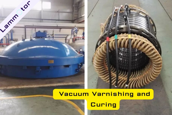
After impregnation, the stator is baked at low temperature for 3 hours and high temperature for 18 hours (about 24 hours total).
This step solidifies insulation and prevents vibration damage, forming a robust dielectric system inside the stator.
5. Assembly of the High-Voltage Motor
Once both stator and rotor are completed, the High-Voltage Motor Assembly begins.
All major components—stator, rotor, end caps, bearings, and coolers—are precisely fitted together.
Before assembly, the stator bore and rotor shaft are cleaned and checked for concentricity.
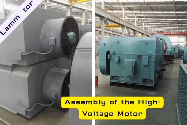
The rotor is then slowly inserted into the stator using a crane to avoid contact with windings.
After mounting end caps and cooling systems (air or water type), alignment and fastening are completed.
6. Factory Testing of High-Voltage Motor
Before shipping, every High-Voltage Motor must pass rigorous factory testing to ensure performance and safety.
Tests include:
- No-load run test: checks smooth start-up and stable operation.
- Electrical tests: voltage, current, power factor, and insulation resistance.
- Temperature and noise measurement: ensures operation within design limits.
- Vibration and balance test: verifies rotor dynamic balance.
- Withstand voltage and leakage test: confirms insulation system integrity.
After all tests are passed, a detailed inspection report is issued.
The motor is cleaned, painted, and packed for delivery.
From Lamination to Power: The Essence of High-Voltage Motor Manufacturing
From a thin steel sheet to a powerful rotating machine, every detail reflects craftsmanship and precision.
The accuracy of the High-Voltage Motor Core, the precision of winding, and the reliability of vacuum varnishing together define motor efficiency and lifespan.
If you are seeking professional solutions for High-Voltage Motor Manufacturing, including stator and rotor core customization, contact us today to discuss your project needs.
We provide complete design, prototyping, and mass-production support for High-Voltage Motor and wind power generator Stators and Rotors.