What makes a PMSM rotor not just functional, but powerful, efficient, and safe at high speeds?
As a manufacturer with years of experience in permanent magnet motor rotors, I’ve worked with countless engineers to turn their designs into real-world solutions. Over time, I’ve realized that many designers and enthusiasts are curious about how PMSM rotors are actually built, from structure to material to performance under stress.
This blog breaks down the key technologies behind permanent magnet synchronous motor rotor design. I’ll explain common rotor types, structural features, and practical design strategies, all based on real manufacturing know-how.
Let’s start it.
Three Common Rotor Types of Permanent Magnet Synchronous Motor
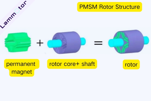
The PMSM rotor typically consists of a laminated iron core, permanent magnets, shaft, and bearings.
The rotor core is similar to the stator core. It’s made from 0.25–0.5 mm silicon steel sheets stacked together to form a magnetic path and reduce eddy current losses.
Depending on the magnet placement, the rotor can be classified into surface-mounted and interior types.
Surface-Mounted (Protruding Type)
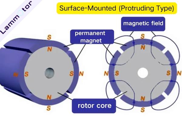
Magnets are directly glued onto the outer surface of the rotor core. The structure is relatively simple and results in a good air-gap flux waveform. However, the magnets are fully exposed to centrifugal force during high-speed rotation, making it necessary to use protective structures (e.g., sleeves) to prevent damage.
Surface-Embedded
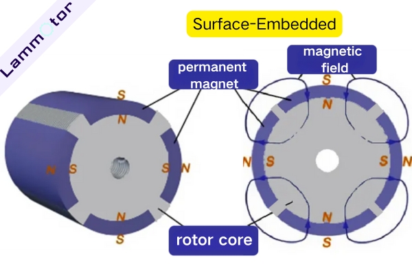
The magnets are placed inside slots near the surface of the rotor. This design provides better lateral support to the magnets compared to the protruding type, enhancing resistance to centrifugal forces. It also allows saliency, which helps with field weakening and high-speed extension.
Interior Permanent Magnet (IPM) Type
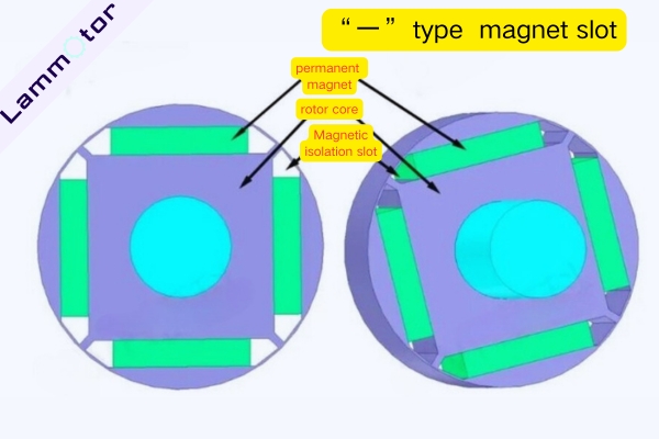
This is the most common structure in EV drive motors. The magnets are fully embedded in pre-machined slots inside the rotor core.
Radial arrangements include:
“一” type: Simple structure and easy to install but causes more air-gap harmonics.
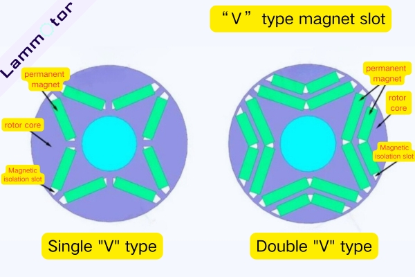
“V” type: Better magnetic utilization and fewer harmonics, but more complex.
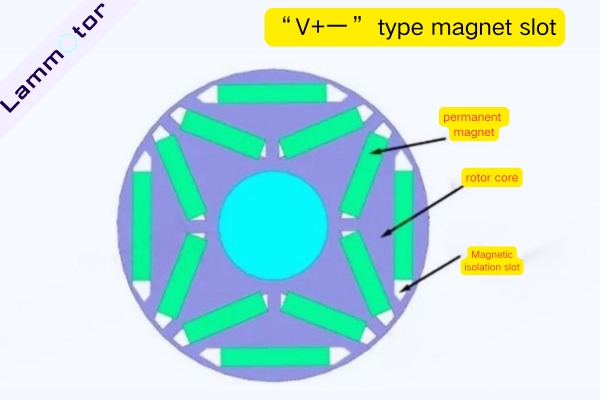
“V-一” hybrid: Further reduces harmonics and increases reluctance torque, improving power density—but adds structural complexity.
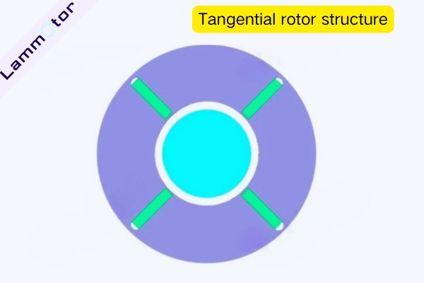
Tangential Rotor Structure
Cost more to manufacture and have higher leakage flux, so they often include magnetic barriers or air slots. The advantage is that the magnetic flux per pole is enhanced through parallel flux paths.
Hybrid Rotor Structure
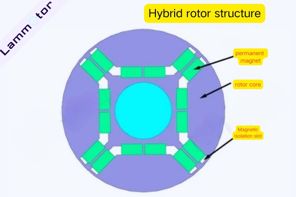
Combine the benefits of radial and tangential types. However, they are harder to produce, more expensive, and may slightly reduce the mechanical strength of the silicon steel laminations.
Real-World Examples of Rotor Layouts
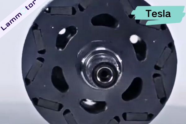
Tesla’s 3D6 motor uses a single V-shape magnet arrangement.
Xiaomi’s SU7 adopts a dual-V layout.
BYD Han L’s 580 kW motor uses dual-U-shaped magnet slots.
These are just a few typical designs. In practice, engineers often adjust these layouts or create new ones based on specific project needs.
Strength Analysis of High-Speed PMSM Rotors
Although sintered NdFeB magnets offer excellent magnetic performance, their tensile strength is much lower than their compressive strength. At high speeds, centrifugal force becomes the primary mechanical threat.
Choosing the Right Structure
The IPM structure is ideal for high-speed rotors because the magnets mainly endure compressive stress, while the rotor core walls absorb most of the centrifugal force.
Sleeve Protection Techniques
In certain designs, especially surface-mounted types, a high-strength sleeve is crucial for safety.
Two main types of sleeves are used:
1. Non-magnetic steel sleeves
These offer strong mechanical support and mature manufacturing methods (e.g., interference fit). However, they can introduce additional eddy current losses, especially at high speed, so thickness and heat dissipation must be optimized.
2. Carbon fiber composite sleeves
These are light, non-magnetic, non-conductive (minimal eddy current loss), and have a tunable thermal expansion coefficient—ideal for matching magnet expansion and reducing thermal stress.
That’s why carbon sleeves are used in high-end motors like Tesla’s Model S Plaid and Model X Plaid, where motors can spin up to 20,000 rpm.
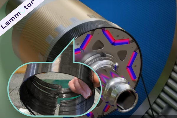
The downside is high cost, complex manufacturing (winding, curing), and long-term reliability concerns.
PMSM Rotor Structural Design Considerations
The PMSM rotor structure is both functional and highly engineered. The core is made by stacking thin silicon steel laminations, which help reduce eddy current loss and improve efficiency.
Lightweight Design & Low Inertia
To reduce rotational inertia and improve motor response (faster acceleration/deceleration), designers optimize rotor core topology with weight-reducing holes or slot shapes, and consider strong but lightweight materials.
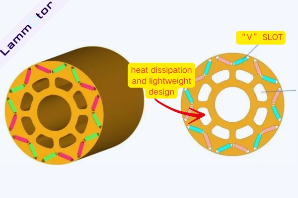
V-shaped slots on the rotor’s outer side secure the magnets during high-speed rotation.
Inner slots are carefully designed to maintain structural strength while reducing mass, further lowering inertia and enhancing dynamic performance.
Skewing and Pole-Shifting Techniques
The rotor may adopt skewed slots or multi-section skewing to reduce torque ripple and electromagnetic noise.
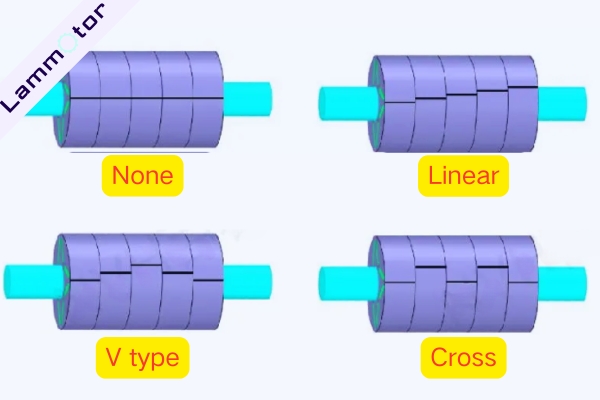
This involves splitting the rotor into axial segments and offsetting each segment’s poles slightly in the circumferential direction.
For example, a 5-section skew means the rotor is divided into five parts, each misaligned by a set angle. The more segments, the lower the cogging torque.
However, increased segmentation also increases axial magnetic force and flux leakage, so engineers must strike a careful balance.
Skewing styles include traditional skewing, V-type skewing, and interlaced skewing.
Contact Us for PMSM Rotor Lamination Stacks.
As we’ve seen, rotor design in PMSMs is far from simple. Every structure—whether it’s a V-slot or a carbon fiber sleeve—directly impacts the motor’s performance, cost, and reliability.
If you’re developing a PMSM and need a trusted partner to manufacture high-quality rotor cores, we’re here to help. With years of hands-on experience and advanced lamination production capabilities, we can bring your design to life.
Contact us today to discuss your PMSM rotor core requirements for electric vehicles.