Have you ever wondered how Direct-driven Wind Turbine Generators work without a gearbox and still deliver high efficiency?
These innovative generators are changing how we convert wind energy into electricity. By eliminating the gearbox, they achieve higher efficiency, lower maintenance, and quieter operation—making them the preferred choice for modern wind power systems.
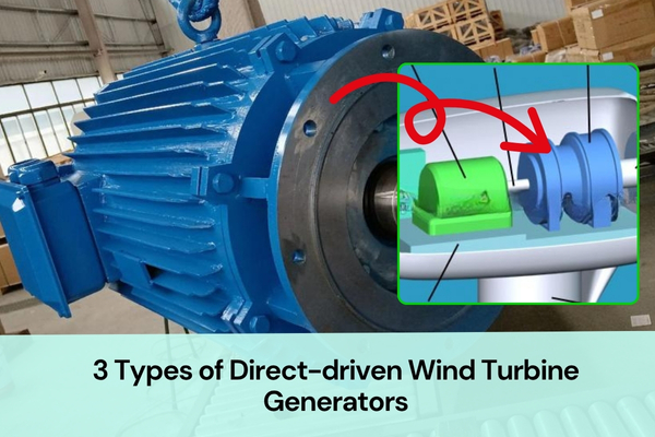
This article introduces the main classifications of Direct driven Wind Turbine Generators, including inner rotor, outer rotor, and axial flux permanent magnet structures. Each type has its own unique magnetic circuit, mechanical layout, and performance characteristics.
Outer Rotor Permanent Magnet Direct-driven Wind Turbine Generator
The Outer Rotor direct-drive permanent magnet synchronous generator is a type of radial-flux generator where the rotor is placed outside and the stator remains inside.
Compared with the inner-rotor design, this structure features the stator windings fixed on the inner core, while the permanent magnets are mounted on the inner surface of the outer rotor shell. This design allows the rotor to be directly connected to the wind wheel hub so that both rotate together, achieving efficient direct-drive power generation without the need for a gearbox.
1. Structural Features and Magnetic Circuit
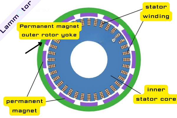
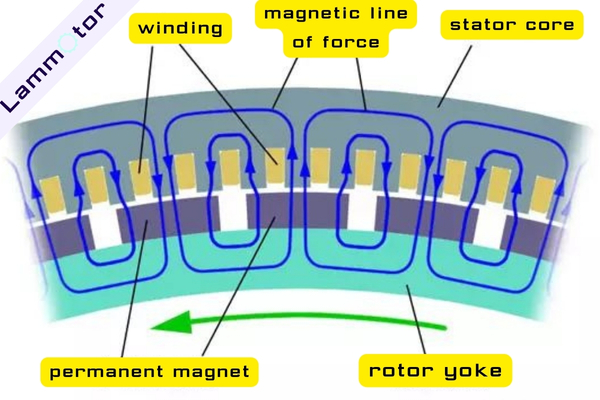
The outer rotor permanent magnet generator adopts a radial air-gap magnetic flux structure. The stator stays stationary at the center, while the rotor rotates outside it. The magnetic flux passes perpendicularly through the air gap relative to the motor shaft — it flows from the permanent magnets, across the air gap, into the stator core, and then closes through the return path.

In this configuration, the stator located at the center is referred to as the inner stator, and the rotor on the outer circumference is called the outer rotor.
When the wind wheel drives the rotor to rotate, the windings embedded inside the stator slots cut the magnetic flux lines, thereby generating an induced voltage and converting mechanical energy into electrical energy.
2. Inner Stator Core and Three-phase Windings
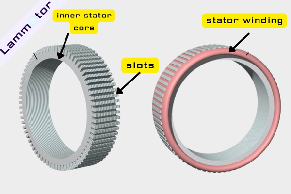
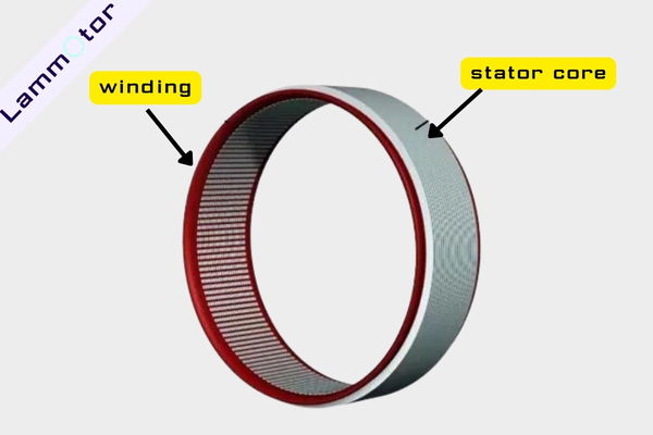
The stator core of the outer rotor generator is made of high-permeability laminated silicon steel sheets. Its outer circumference contains evenly distributed slots for embedding the three-phase windings. The winding layout is similar to that of a conventional three-phase alternator, forming balanced three-phase output voltages.
In a demonstration model, the number of coil slots is often fewer than in an actual production generator. For instance, a large direct-drive generator typically uses an outer rotor with 30 to 40 pole pairs, and the stator contains 180 to 240 slots.
The assembled stator is fixed inside the nacelle base using a strong mounting frame. One end of the frame connects to a flange, while the other end supports the main shaft. This shaft must bear the combined weight of the outer rotor and wind wheel while resisting wind loads, requiring very high mechanical strength and stiffness.
3. Outer Rotor Construction and Magnet Arrangement
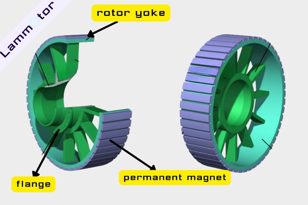
The outer rotor resembles a cylindrical shell made of a highly magnetic material. Along its inner circumference, multiple high-performance rare-earth permanent magnets are evenly distributed in alternating N and S polarities, forming a multi-pole magnetic field with a radial flux pattern.
Because the magnets are fixed securely to the inner wall and supported by a robust structure, this design offers excellent centrifugal resistance, reliable mechanical integrity, and good heat dissipation performance.
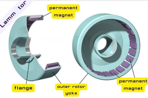
The outer rotor is connected to the main shaft through a hub sleeve and is supported by two large bearings to ensure smooth rotation and high concentricity.
When the wind wheel rotates, the outer rotor spins synchronously, causing the magnetic field to cut through the stationary stator windings and generate alternating current.
4. Assembly and Installation of the Generator
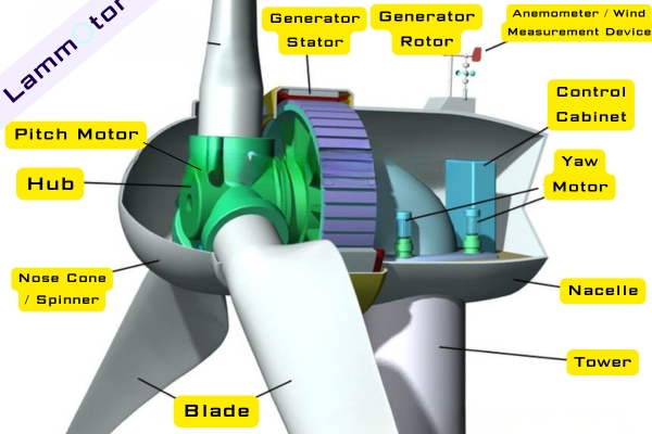
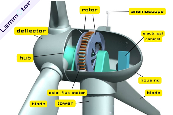
In a wind turbine system, the entire generator assembly is mounted inside the nacelle at the top of the tower. The nacelle base is equipped with a yaw system that automatically adjusts the turbine’s orientation so that the wind wheel always faces the wind.
The generator is lifted and installed inside the nacelle. The base flange and the generator flange are then bolted tightly together to ensure structural rigidity and stability during operation.

Thanks to its compact structure, strong resistance to centrifugal forces, and convenient maintenance, the Outer Rotor Permanent Magnet Direct-driven Wind Turbine Generator is widely used in small and medium-sized wind turbine systems.
Inner Rotor Permanent Magnet Direct-driven Wind Turbine Generator
The Inner Rotor Permanent Magnet Direct-driven Wind Turbine Generator is one of the most common structures used in modern wind energy systems. Its working principle is based on electromagnetic induction—the permanent magnets create a magnetic field, and the stator windings cut through the magnetic lines of force as the rotor turns, inducing electric current.
Unlike conventional asynchronous generators, this design eliminates the gearbox, which greatly improves reliability and overall efficiency.
1. Structural Features and Magnetic Circuit Design
This type of generator uses a multi-pole radial-flux configuration, where the magnetic flux in the air gap is perpendicular to the shaft. The rotor is located inside, surrounded by the outer stator, hence the name “inner rotor.”
To enable low-speed direct-drive operation, the rotor is typically designed with many magnetic pole pairs (for example, 50 or more), allowing the generator to produce the required frequency at a low rotational speed.
The magnetic field lines travel radially through the air gap between the stator and rotor, forming a closed magnetic circuit. This structure ensures efficient electromagnetic coupling and high torque output even at low speed.
2. Stator Core and Winding Structure
The stator core is built from laminated silicon steel sheets with high magnetic permeability. Its inner circumference is evenly slotted to accommodate the embedded windings. These windings are arranged in a symmetrical three-phase configuration, with each phase composed of multiple coils connected according to a fixed sequence to form a balanced three-phase output.
For clarity in demonstration models, the number of stator slots is sometimes reduced compared to real machines. For instance, a generator with 50 pole pairs typically has 150 or more stator slots in full-scale production.
The stator assembly is mounted inside a rigid frame, which also carries the main shaft, flange, and other mounting structures for coupling the wind wheel and generator body.
3. Rotor and Permanent Magnet Structure
The rotor adopts a multi-pole salient-pole structure. Multiple high-energy permanent magnets are mounted along its outer circumference with alternating polarities (N and S), creating an alternating magnetic field pattern.
The magnetic flux passes through the air gap into the stator core, and when the rotor rotates, the stator windings cut through these flux lines to generate alternating current.
The rotor yoke is fixed to the main shaft via a robust supporting hub. The small air gap—typically around 1 millimeter—ensures high magnetic coupling efficiency and reduces losses.
4. Generator Assembly Inside the Nacelle
Inside the nacelle, a heavy-duty frame supports the entire generator assembly. A yaw motor mounted beneath the frame allows the nacelle to rotate horizontally, ensuring the turbine always faces the wind.
The stator is mounted to the frame, while the rotor connects directly to the main shaft.
With its compact design, high transmission efficiency, low maintenance, and strong reliability, the Inner Rotor Permanent Magnet Direct-driven Wind Turbine Generator is widely used in both medium- and large-scale wind turbines.
Axial Flux Direct-driven Wind Turbine Generator
The Axial Flux Direct-driven Wind Turbine Generator uses a flat, disc-like structure where the magnetic flux flows parallel to the shaft. Both the axial flux stator and rotor are circular plates, forming a thin and efficient design ideal for low-speed, high-torque applications.
(1) Single Stator, Dual Rotor Structure
This is the most common configuration. The stator is placed in the middle, sandwiched by two outer rotors with permanent magnets. As the wind wheel rotates, the magnetic flux passes axially through both sides of the stator, generating electricity in the coils.
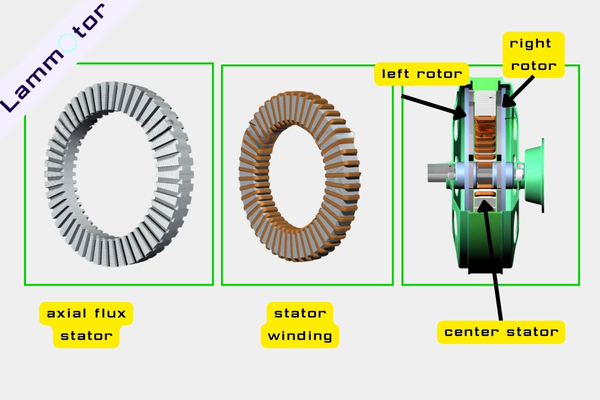
This structure has dual-sided magnetic excitation, high efficiency, and a compact size. It’s widely used in Direct-driven Wind Turbine Generators and vertical-axis wind turbines.
(2) Dual Stator, Single Rotor Structure
In this design, two stators are placed on both sides, while a single rotor with permanent magnets is mounted in the center. The magnetic flux travels axially from one stator, through the rotor, to the other stator, forming a closed loop.
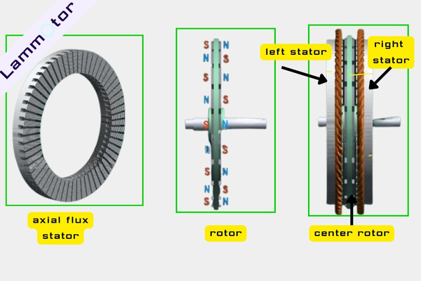
This layout provides high power density, balanced forces, and smooth operation. It’s suitable for high-efficiency axial flux Direct-driven Wind Turbine Generators used in advanced wind power systems.
Contact Us for Manufacturing Wind Power Generator Stator And Rotor Cores
Direct-driven Wind Turbine Generators represent the future of efficient and sustainable wind power. Whether it’s the inner rotor, outer rotor, or axial flux design, each brings unique advantages in structure, performance, and maintenance.
Which type do you think fits best for your wind power project?
If you need custom stator and rotor cores for Direct-driven Wind Turbine Generators, contact Lammotor today.
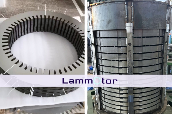
We specialize in manufacturing precision motor lamination stacks, rotor cores, and stator assemblies for high-efficiency wind generators and high-voltage motors.
👉 Reach out to us anytime to discuss your design or manufacturing needs.